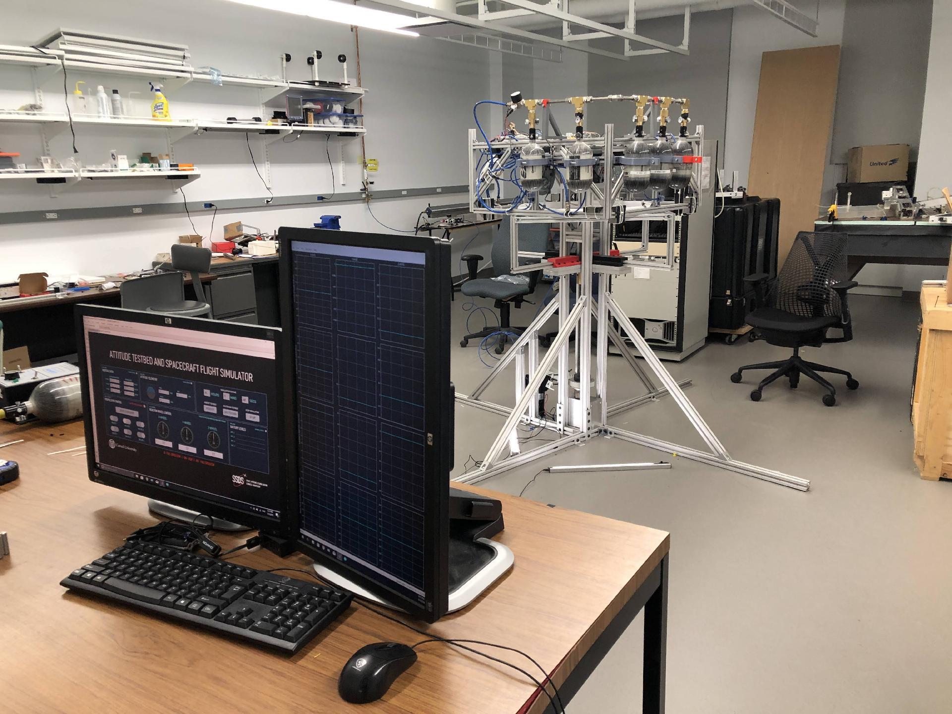
Built for Cornell's Space Systems Design Studio, this remotely controlled testbed uses six cold gas thrusters and three reaction wheels to simulate multi-axis orbital dynamics of spacecraft in a friction-free environment.
Simulating Outer Space
This testbed provides a hardware platform to test spacecraft attitude control algorithms in a frictionless environment simulating outer space. The platform consists of an aluminum chassis levitated on a spherical air bearing and
uses six cold gas thrusters and three reaction wheels to maneuver. Our team was advised by the former NASA Chief Technologist, Dr. Mason Peck.
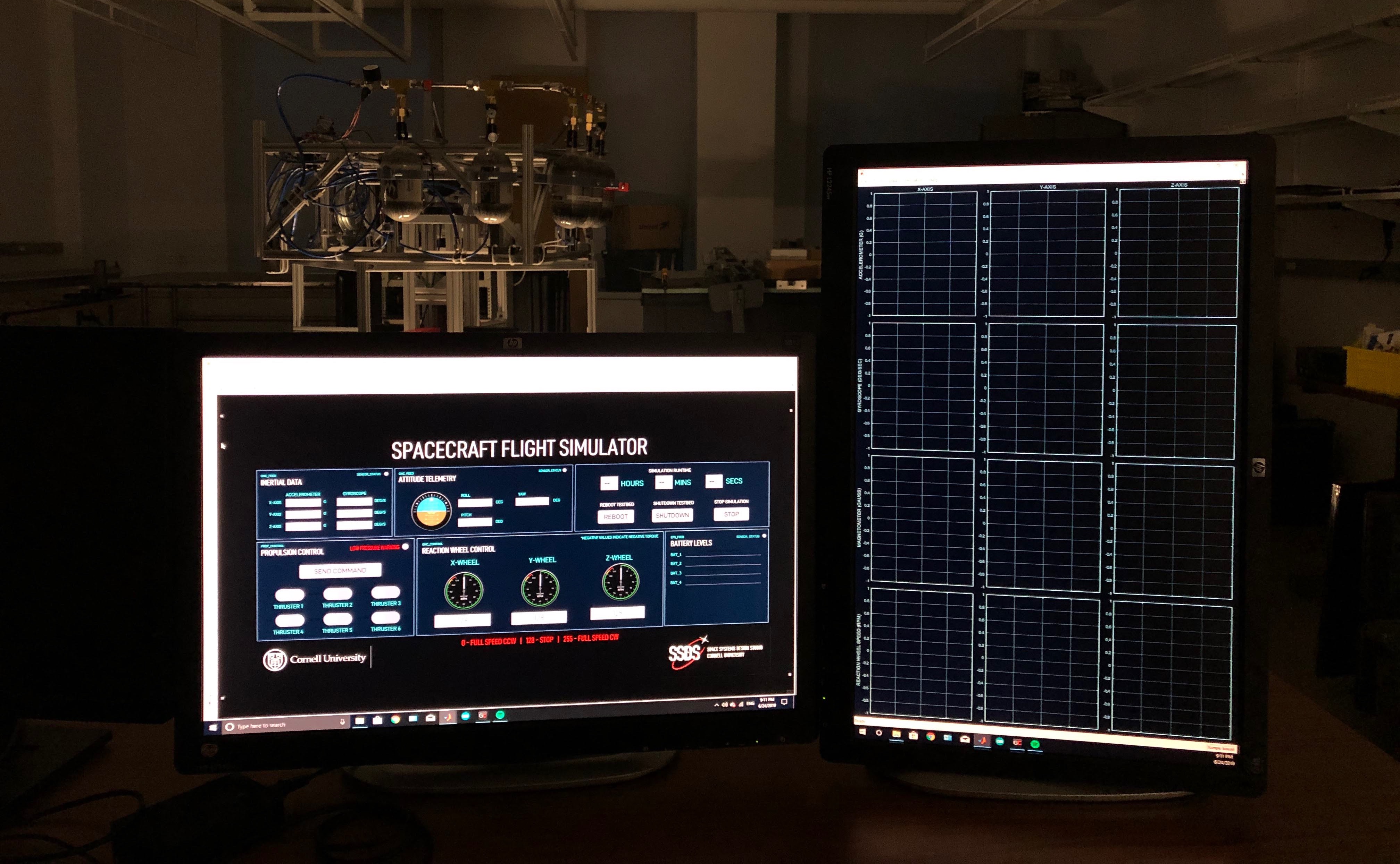
Air bearing levitates testbed to create friction-free environment The simulator maneuvers using three reaction wheels (motors that turn spacecraft through gyroscopic effects) and six cold gas thrusters. The electronics are controlled wirelessly from a nearby computer with a custom-built graphical
user interface.
Complete lab test setup of the simulator and testbed The Spacecraft Flight Simulator and Attitude Testbed provides a lab environment to test autonomous attitude control algorithms for the small spacecraft developed in our research lab, as well as provide Cornell engineering
professors with a hands-on instructional platform for advanced spacecraft control students.
Hardware and Design
Explore testbed components and subsystems.
Simulink Control Station
Design
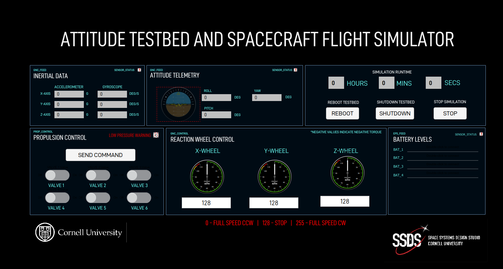
Significant effort was invested in ensuring that the user interface was aesthetically pleasing and evoked in users the excitement of space travel. The typography, color palette, and overall design was inspired by UI design in popular
science fiction films with heavy influence from Territory Studio's VFX work on the 2015 film The Martian. The Simulink Aerospace Instrumentation blockset was
used to provide operational instrumentation graphics such as an artificial horizon (which was fed with a vector containing roll, pitch, and yaw components) and RPM indicators to display reaction wheel speed. Unfortunately, further
artistic liberty was heavily limited by the design constraints of Simulink.
User interface for the spacecraft flight simulator
Functionality
The user interface allows operators to specify a combination of thruster activations and reaction wheel speeds which will be commanded to the testbed at a button press. The dashboard also updates with realtime inertial and attitude
telemetry, reaction wheel speeds, and other system status metrics. There are also failsafe functions that command the onboard flight computer to execute bash scripts that shutdown or reboot the testbed.
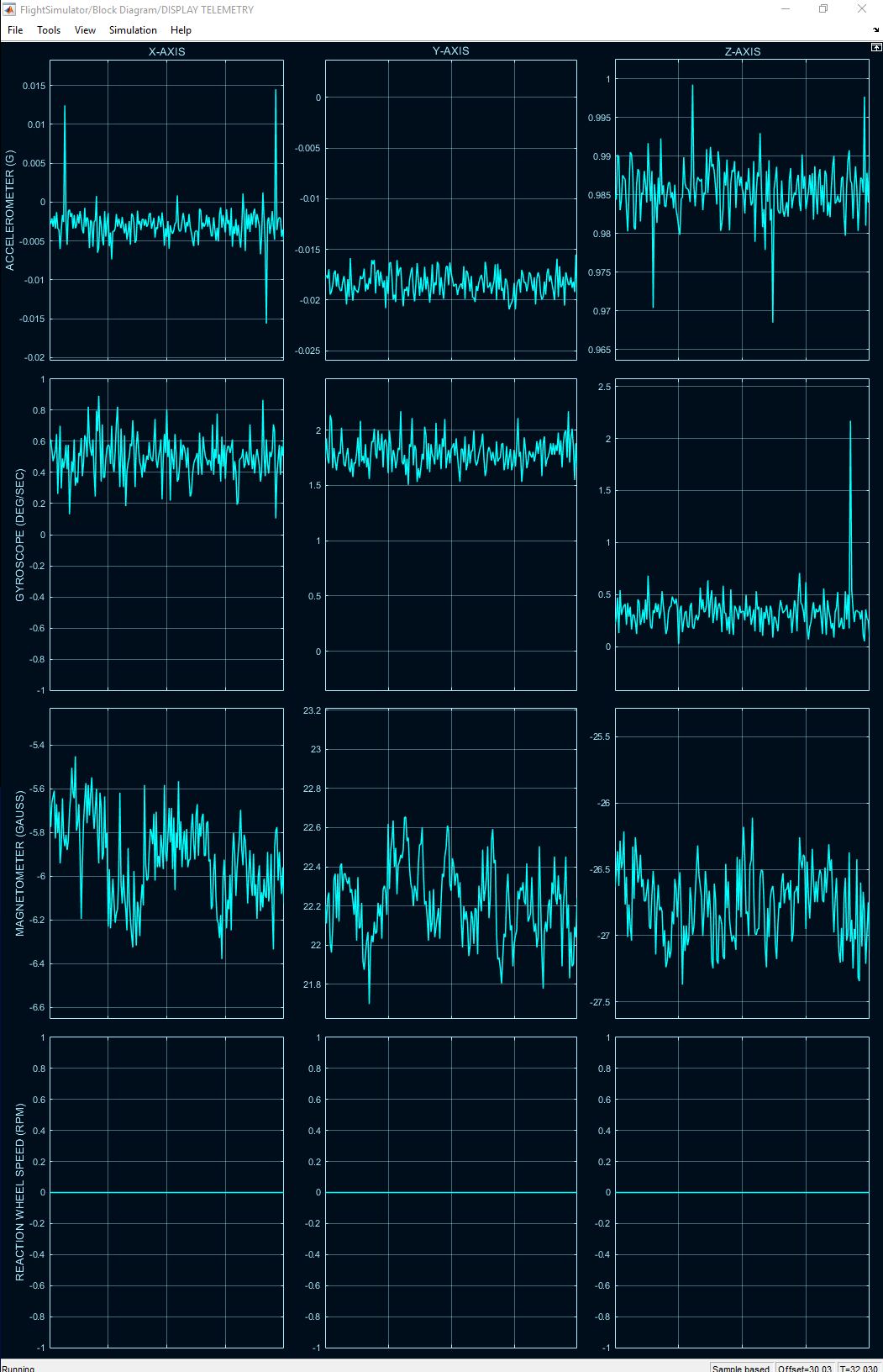
Realtime telemetry visualization
The FLIGHT COMPUTER retains the following roles:
Receives and interprets commands sent wirelessly to the testbed by an operator
Sends instructions to the REACTION WHEEL CONTROLLER and THRUSTER CONTROLLER to execute operator commands
Receives realtime telemetry from the inertial measurement unit (IMU) and pressure sensor
Detects pulse information from three optical tachometers and calculates corresponding reaction wheel speed readings
Transmits inertial telemetry, reaction wheel speeds, and pressure readings back to the operator
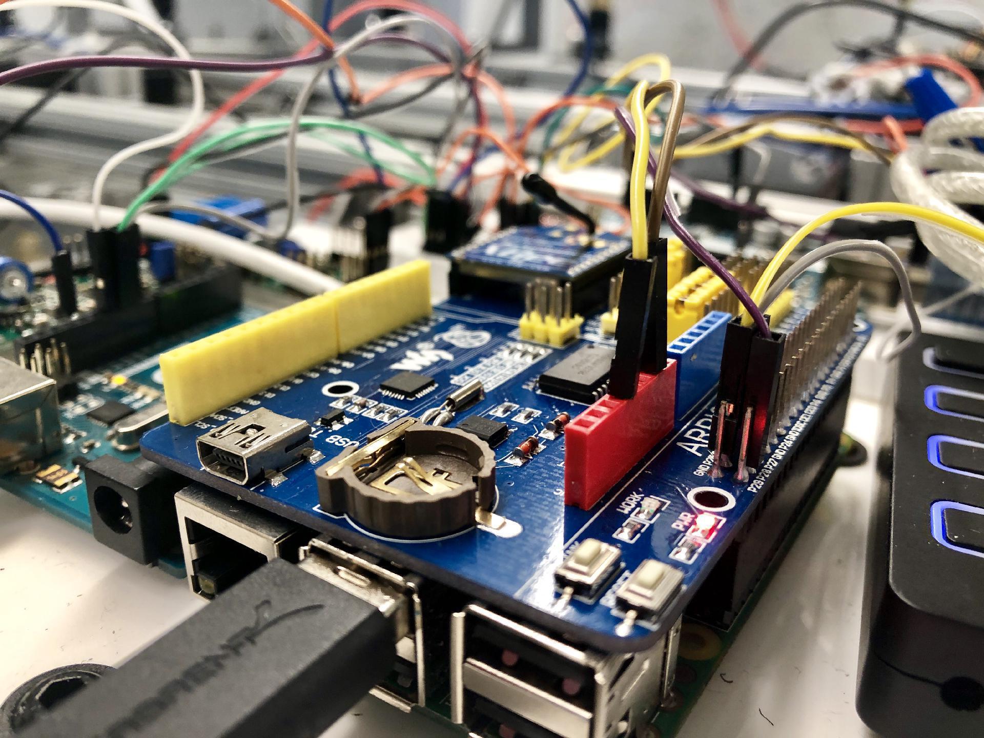
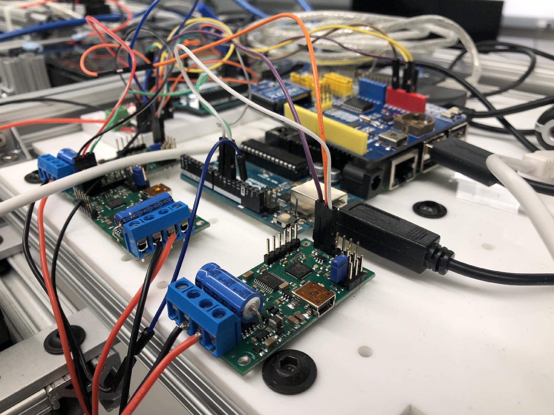
Raspberry Pi flight computer with XBee adapter shield for wireless bidirectional communication
Switching from Arduino Due to Raspberry Pi
Previous teams' designs called for an Arduino Due to act as the flight computer. However, after compiling a requirement set for the flight computer, I realized that an Arduino Due
is not sufficient to realize the requirement set and instead opted for a Raspberry Pi 3B+. This switch enabled me to take advantage of a number of new capabilities including multithreading (enabling multiple processes to run concurrently,
a desired trait for realtime hardware applications), increased clock speed for faster code execution, and the benefit of an entire Linux-based embedded operating system fully contained on the testbed. Each Arduino microcontroller
acting as a peripheral device was plugged directly into the Raspberry Pi USB hub and would achieve bidirectional communication with the flight computer over a UART bus.
Transmitting Telemetry
A primary task of the flight computer is to relay telemetry from the onboard IMU sensor back to the operator. The flight computer achieves this by reading serial data from the IMU reader microcontroller
to gather inertial telemetry and using a FIFO to collect reaction wheel speed calculated by another Python script running in the background. The program then compiles an ASCII string and transmits it to the operator over the local
XBee link.
Transmitted strings containing wheel speeds and inertial telemetryEach line carries information about the speed of each reaction wheel, and accelerometer, gyroscope, and magnetometer readings in three axes from the
IMU sensor. This serial stream is captured and parsed in Simulink where the resulting information is displayed to the operator in a readable manner.
Persistent Serial Device Identification
Each COM device had to be configured in the Raspbian kernel to always be identified with a constant name. However, the operating system randomly assigns names (e.g., /dev/tty0)
depending on which Arduino was recognized first. I introduced u-dev rules to capture uniquely identifying id values for each connected COM device and used SYMLINKs to create an identifying name (e.g., /dev/imu_reader, /dev/motor_controller,
etc.) that uniquely and persistently identifies each microcontroller.
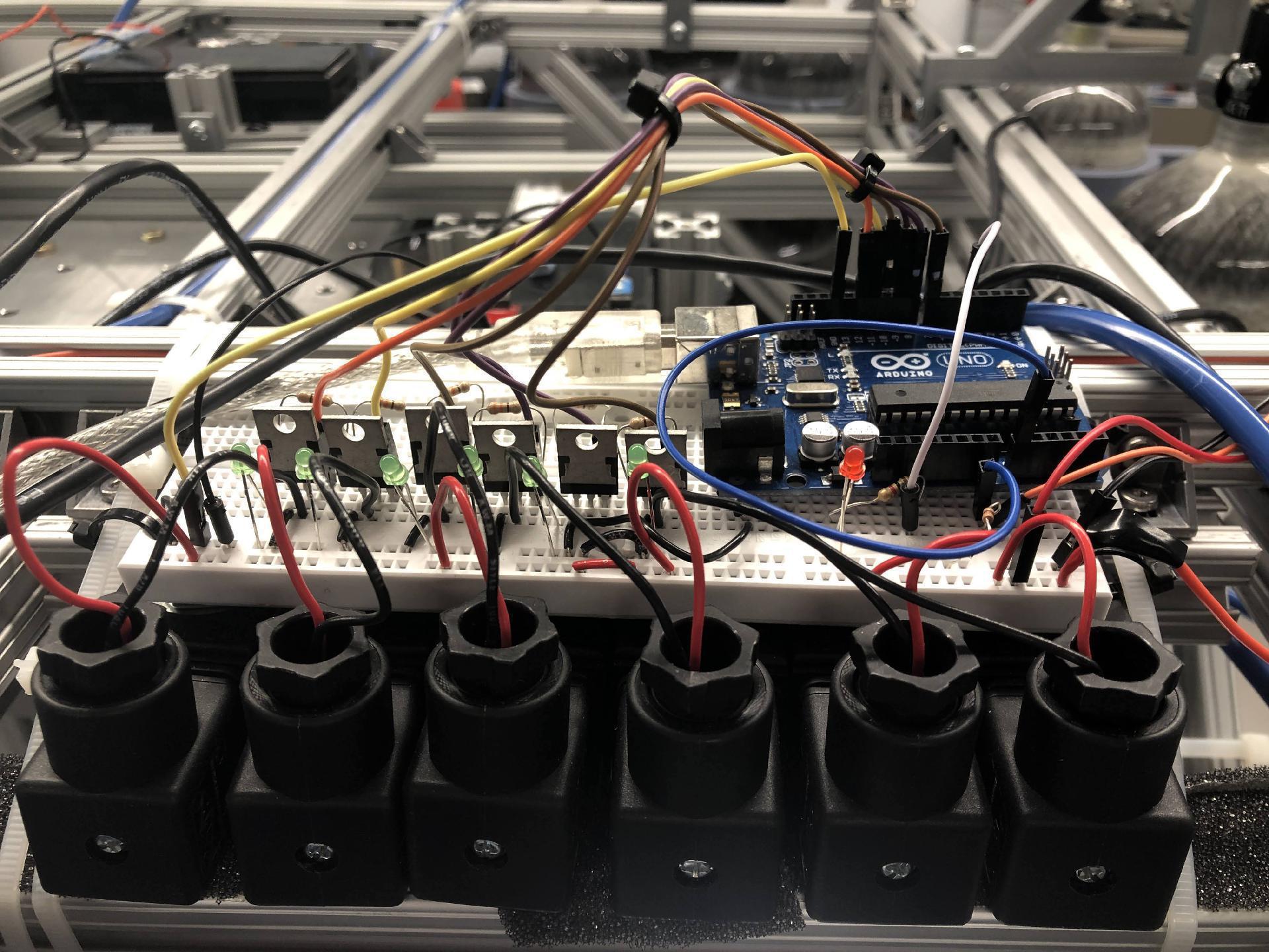
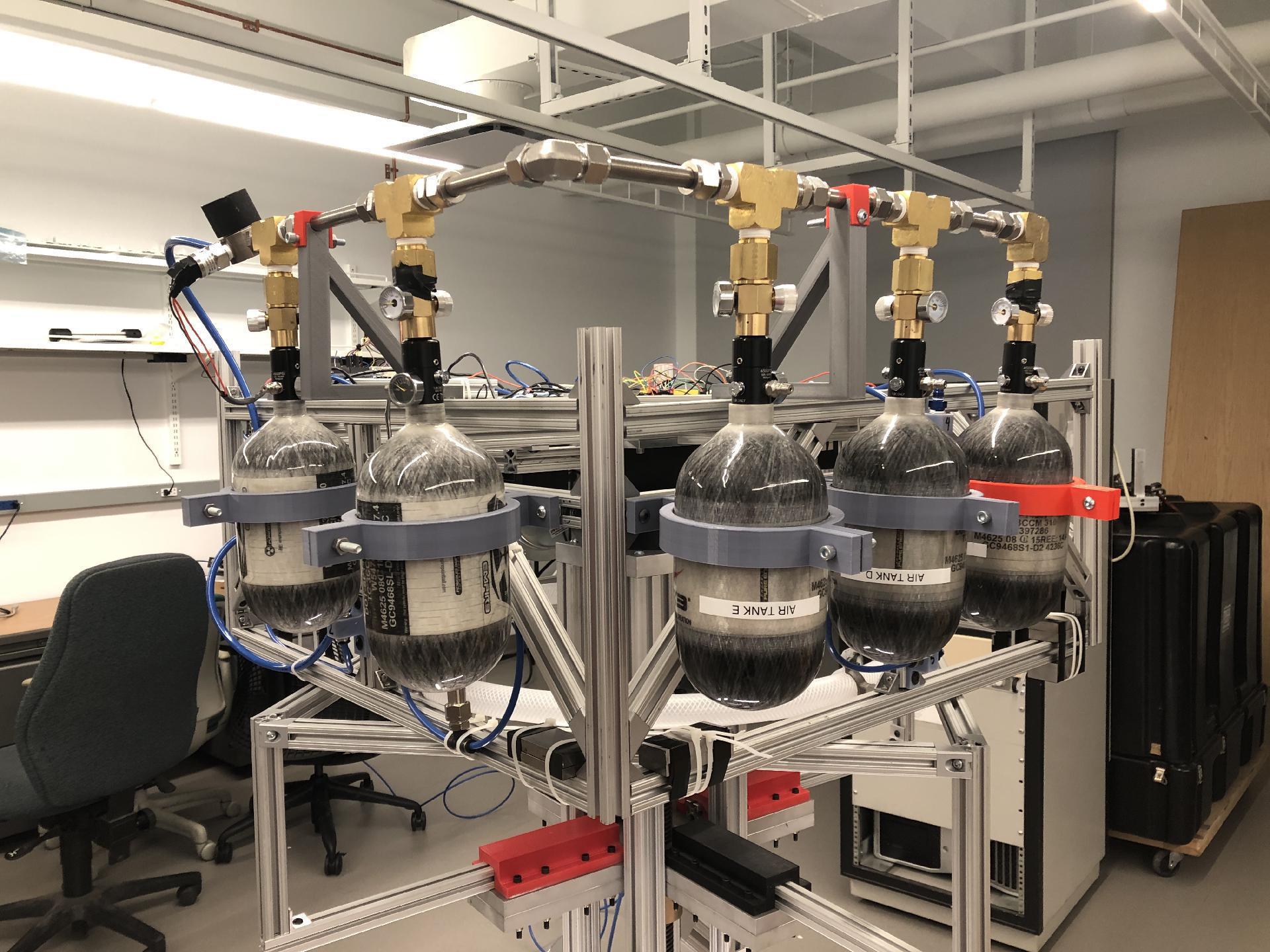
The six solenoid valves controlling each of the six thrust outlets are each connected to a logic-level MOSFET driven by an Arduino microcontroller. Code on the microcontroller limits each thrust duration to 200 ms.
MOSFET drivers to control thrustersThe microcontroller controlling the propulsion subsystem is also connected to a pressure transducer which monitors the air pressure within the manifold that channels air from the tanks
to the thruster outlets. If the pressure dips below a certain threshold, an LED signalling that the tanks need to be refilled. The warning light turns off when the air pressure returns to its nominal range.
Transducer in-line with manifoldOnboard compressed air tanks
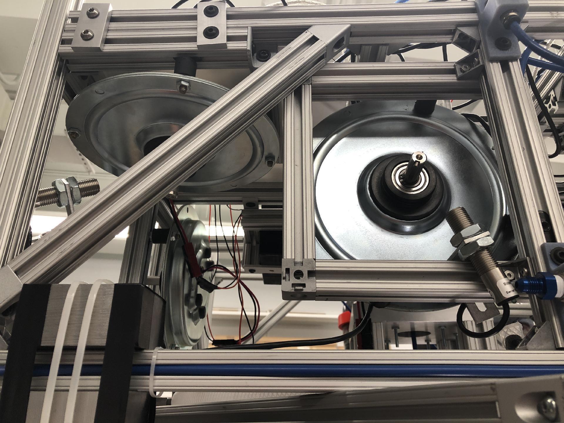
The testbed contains three high-torque DC pancake motors that act as reaction wheels. The reaction wheels are affixed orthogonally to each other to effect torques around three axes.
Reaction wheels and optical tachometersAn optical tachometer was carefully aimed at the spindle of each motor (which held a piece of reflective tape) to count revolutions. The optical tachometers were connected electrically
to the flight computer's GPIO, where a pulse resulting from one revolution would trigger an interrupt service routine that updates an RPM value and sends it to the operator. Additionally, each reaction wheel was driven by a motor
driver that actively monitors temperature, voltage, and current and cuts power to the load when a prespecified shutoff event is detected.
Motor drivers and Raspberry Pi flight computerConstraints were also placed on the brake ability of the reaction wheels (i.e., limits for acceleration/deceleration were put in place) to prevent large, sudden current
draws. The reaction wheel direction and speed are both controlled by an 8-bit integer; a value of '128' sent by the operator to a reaction wheel on the testbed corresponds to zero rotation, '255' to full-speed (3600 RPM) clockwise,
and '0' to full-speed counter-clockwise.
Future Work
Autonomous (Closed-Loop) Control
Having built and successfully demonstrated open-loop control on the testbed to faculty members in the Sibley School of Mechanical and Aerospace Engineering, students from Professor Mason Peck's graduate spaceflight course were tasked
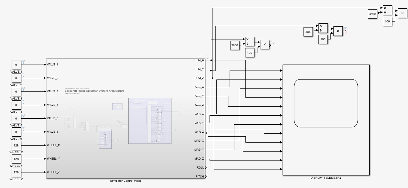
with creating a closed-loop attitude control algorithm in simulation and deploying the controller to our hardware testbed for verification. The Simulink control program may be simplified to a single subsystem that effectively acts as a
plant in a closed-loop control system.
User interface as control plantA controller block may interface with the plant to achieve closed-loop and hardware-in-the-loop control. The controller block should consist of nine outputs: six valve state instructions (0 or
1) and three reaction wheel speed instructions (0-255). The block outputs accelerometer, gyroscope, magnetometer, and reaction wheel speed data in all three axes.
Custom PCB Integration
While fully operational, the electrical hookups on the testbed (i.e. jumper wires and solderless breadboards) are consistent with those of a preliminary prototyping phase. A refined design consists of a single PCB that integrates
all the wiring and electronics with bold, clear silkscreen labeling.
Our Team
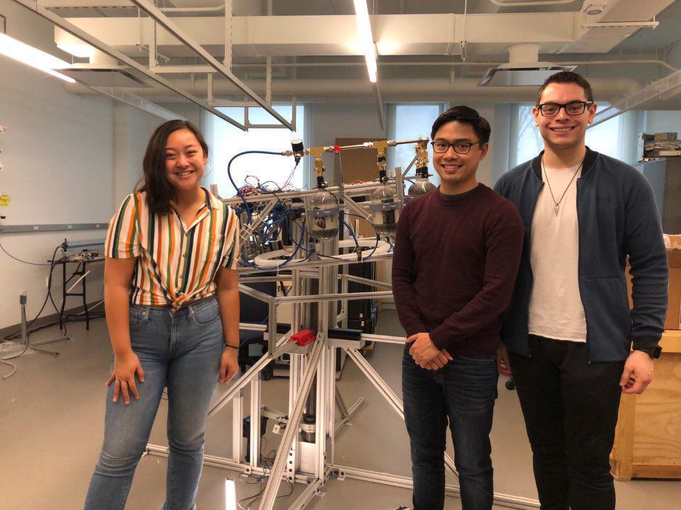
Testbed Team (left to right) — Bettina Aristorenas (Team Lead, Mechanical Engineer), Paolo Arguelles (Electrical & Computer Engineer), and Zach Tretler (Mechanical Engineer)